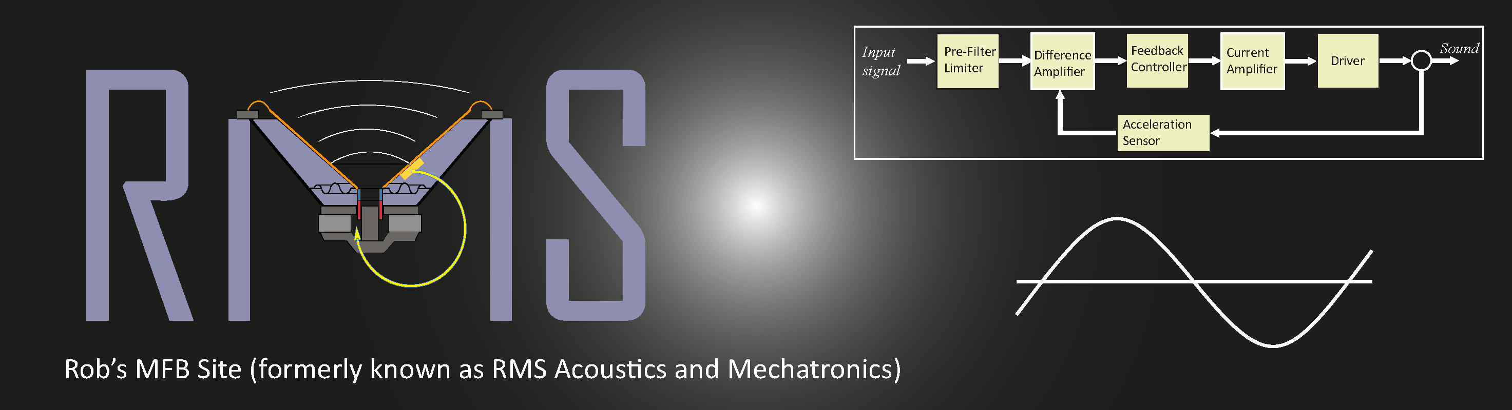
| Home |
Mechatronics |
About RMS |
DMC Sub |
Audio Design |
Education |
Kits & Parts |
Errata in book:
The Design of High Performance Mechatronics (1st edition)
Maintained until Oktober 2013
The list is divided in three categories: (1) serious errors that need attention and more words to explain, (2) small errors, like typo's that can be interpreted wrongly or where the result is OK but not the method and (3) insignificant errors like a comma or a linguistically less fortunate formulation. Changes are marked in bold or explained in words.
1: Major errors
Resonance, damping and natural frequency
Page 103, the sentence before Eq 3.35: In presence of damping the value for Ct at this frequency....(maximum omitted); Eq 3.35 will be changed into |Ct|ω0/Cs=1/2ζ. After Eq 3.35 a more thorough reasoning will in a next printing of the book be added showing that at values for ζ below ≈0.2 this value is approximately equal to the maximum for the transfer function (|Ct|ω0=|Ct|max) but with higher values of zeta the frequency where the maximum value occurs will shift to lower frequencies and at ζ>=0.7 the maximum will be at 0Hz with a value of one, as shown in the figure below. This frequency, where the frequency response becomes maximum, is called the "damped resonant frequency" ωd,r and is slightly different from the "damped natural frequency" ωd,n that is originally presented in Section 3.2.3.2 as the real resonance frequency ωd. In the free moving situation the natural frequency is 0Hz when ζ>=1.
The difference in naming (resonance vs natural) is on purpose because of this difference in frequencies. "Resonant" refers to the response on a force stimulus of a certain frequency where at resonance the response is maximum. "Natural" refers to the behaviour of a free moving system after an impulse or step stimulus so without a continuous stimulus at a certain frequency. The difference between both frequencies ωd,r and ωd,n is caused by the force stimulus that is only present in the resonant situation, at a frequency different from ω0 where the force is out-of phase with the velocity, as shown in Figure 3.13 of the book. This causes a less efficient transfer of energy at this lower frequency. Without damping both frequencies will be equal to the undamped natural frequency ω0.
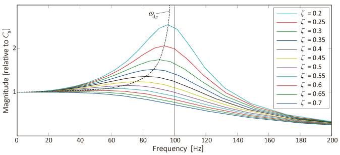
Figure: An increasing amount of damping will decrease the frequency where the maximum magnitude of the frequency response occurs. This is best viewed on a linear scale.
With the above the following changes should also be applied:
Page 106-108: ωd needs to be replaced by ωd,n and the first and second line above Equation 3.41 will read:....contains ωd,n ,the damped natural frequency. When these...
Page 110, line below Eq 3.51: The direct relation of Q with the resonance peak in the Bode plot of a weakly damped system on a forced frequency stimulus is shown when combining.....Eq... with Eq... and taking|Ct|ω0=|Ct|max.
Page 111: ω0 must be replaced by ωd,n as the energy lost per cycle refers to the free moving situation without continuous excitation.
Combination of eigenmodes in different directions:
Page 134, Figure 3.26 only shows a very unique situation where at high frequencies the magnitudes of the movements of both eigenmodes are equal. Only in that situation the resulting response would obtain a slope of -4 at higher frequencies like in the previous Figure 3.22 for a single directional case with two coupled bodies. In reality this will however never be the case when eigenmodes in different coordinate directions are combined and therefore the figure should be changed as shown below. The resulting response will at higher frequencies follow a -2 slope as a combination of both mass-lines. Note that the combined response is shown in dotted lines to enhance the recognisability from especially the phase responses of the separate eigenmodes:
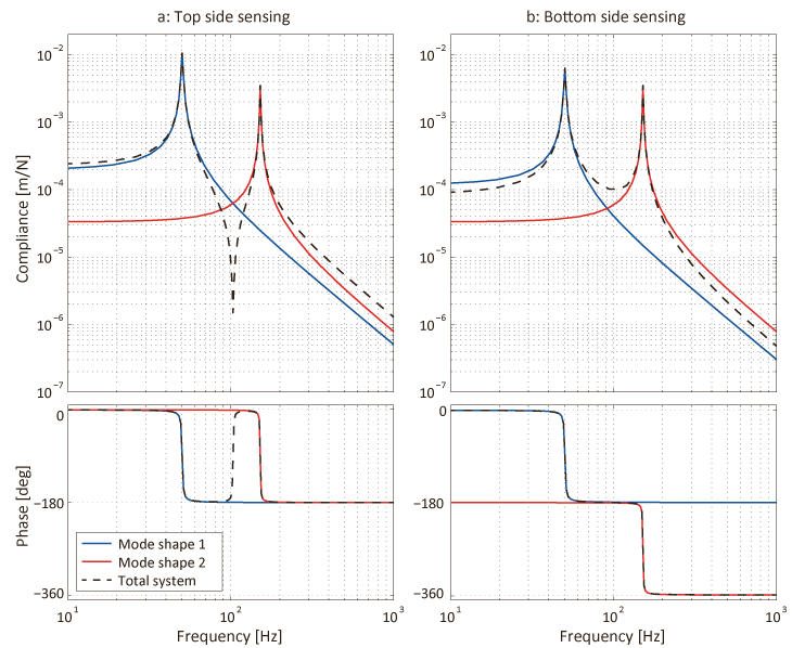
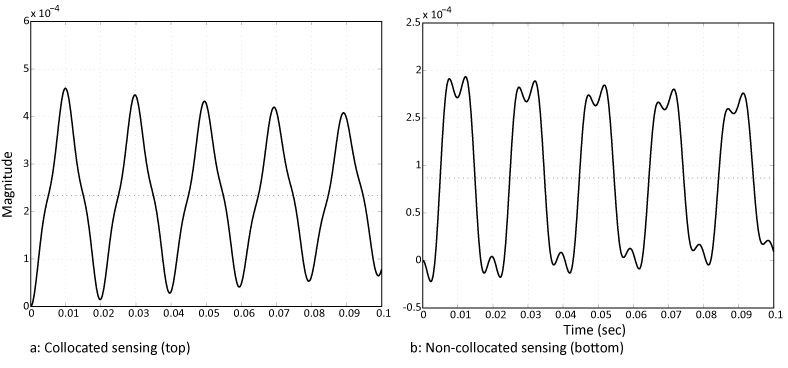
Page 133, 8th line from below (related to the above): At higher frequencies above the second eigenfrequency the slope of this combined response becomes -2 with a -360o phase difference. This is a real non-minimum phase system as can be seen from the following response in the time domain:
 .
.
The first figure shows the response when measuring at the top of the body while the second figure shows the response when measuring at the bottom. In the latter case the initial response is in the opposite direction to the force, which is a typical characteristic of non-minimum phase behaviour. The resulting combined transfer function also shows a typical "unstable" zero in the right half of the Laplace plane.
(The 6th until 2nd sentence from the bottom between "While... " and "... single body" will be omitted as it is meaningless.)
2: Minor errors
Page 40, 3rd line from bottom of first paragraph:...over the equidistant plane from both charges equals zero along the plane and the....
Page 52 Eq 2.18: Integral from t0 to t1
Page 41, second line from the bottom:...positive numbers , when qx=positive and the E field is.....
Page 53, 3rd line below Eq 2.20: It is a well know term in electrical engineering...
Page 58, fourth line below Eq 2.28: 160.109 Pa
Page 70, 7th nline below caption: the summed first five terms....
Page 73, Eq 2.44: L{dx(t)/dt}=sx(s)+x(t=0)=...
where x(t=0) is neglected because the Laplace transform is used to determine the frequency domain behaviour of the system.
Page 94: kr should be kp, as this relates then better to the control part. Also the second and third line below the bullet points should read as: This means that a negative feedback position controller with a constant gain kp acting.....
Page 95 and further: Sec 3.2 deals with a rigid-body situation and in a next version the free body diagram will be used to derive the equations. Sec 3.3 will be renamed into non-rigid body dynamics and eigenmodes as multi-body dynamics is difined as coupled masses with hinges.
Page 111, Eq 3.55 : The damping factor c is missing before the integral; The line below Eq 3.56: the root sign above km/c is extended too far. It should be only above km
Page 117, first paragraph below figure: when compared to the situation with Q=100
Page 125, 6th line from bottom: ....deformations of these eigenmodes and are described by the shape function in the multi- dimensional working space.
Page 127, 1st line: the numerator of the last term:
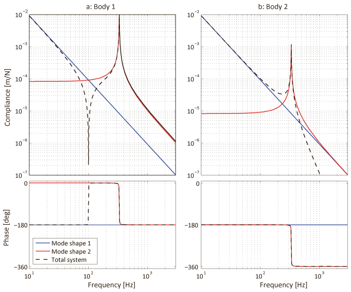
Page 127: The use of the face C for the mass ratio factors is confusing as it looks like compliance while it has no relation with compliance. Also the expression in the last paragraph is confusing where the movement of the second body is told to be derived by subtracting the second eigenmode from the first eigenmode. As the movement of both eigenmodes are physically always added it is better to say that movement of the second body is derived by adding the inverted second eigenmode. This inversion introduces an additional -180o phase shift and Figure 3.22. would then become as follows:
Page 140, 3rd line below Eq 4.1 of+/-root(|k|/m) (absolute value of k)
Page 141, 2nd line from top: positive stiffness of the negative feedback controller can compensate the negative stiffness of the plant when....
Page 143, First line below Figure 4.4: ....integers with m<=n for a "strictly proper system". A strictly proper system is a system that can be made in reality. The rule that a proper system will aways have more poles than zeros is based on the fact that no real system can ever be made to act with a finite response at infinite frequencies. This means that any part of a control system that can be physically separated should in itself have more poles than zero's and this implies that a real system will have far more poles than zeros because for instance all electronic parts are separable. In practice most of these poles will be outside the frequency range of interest. An equal pole and zero cancel....(etc)
Page 167, Figure 4,18: The feedback path should start at y iso the summation point
Page 178, 1st line below caption: Therefore in this example:
Page 179, Figure 4.24: The downslope of T(s) at higher frequencies should be -2.
Page 184, Figure 4.27, 6th line of caption: of kp is added....
Page 195, 9th line from top: by means of decoupling matrices....;second line above Eq 4.44: the (t) term to distinguish it from the frequency domain as the state space...
Page 196, 5th line below Figure 5.35: feed-through transfer gain D.
Page 197, first line from top:, like a spring (....), a body (....), a capacitor (E=0.5CV2) and an inductor (E=0.5LI2).
Page 205, 5th line from top: only the values of the model parameters are identified...
Page 225, Eq 5.13 after the arrow: Bw,i should be Bw
Page 257, Section 5.3: Reluctance force actuation.
Page 294, Equation 5.135: Vp should be Vi
Page 324, Eq 6.10: P0=....=R0Vi2/....=.... (R0 added)
Page 341, Eq 6.35: F(ω)=....=....=1/-ω2LC+1 (minus added)
Page 343, last lines: and quality factor Q
Page 491, 1st line below caption: Figure?? should be Figure 7.18
Page 541, 8th sentence from below (equations) should be numbered and the second equation should read: ![]()
Page 567: Equation 8.31 is wrongly derived as Vi should have been written as Vi=Vdc+V̂i sin ωit=Vdc+V̂i sin 2πfit. This would result after the multiplication with Vc into Va= VdcV̂c sin 2πfct + V̂iV̂c*the summed cos terms/2 (where 2pi is missing at the second cos!)
Page 677, Eq 8.88: To be consequent λ-2 should have been written as σ2.
3: Insignificant errors
Page xxii, second line from bottom: of less than a nanometre
Page 23-29, subsection numbering: 1.3.0.3 should be 1.3.1; 1.3.0.4 should be 1.3.2; 1.3.0.5 should be 1.3.3: 1.3.0.6 should be 1.3.4
Page 26, second bullet: In the "System Design" layer,
Page 34, first paragraph: Dot missing
Page 52, 12th line below Sec 2132: dot missing; next line: mechatronic
Page 54, 1st line above Eq 2.23: following reasoning,
Page 57, 5th line of sec 2.2.1: different kinds of...
Page 62, 5th line below figure: in reality be..
Page 63, 5th line from the bottom:. Because...
Page 64, 4th line under Figure 2.15: for the upper..., 5th line under EQ 2.29: are shown
Page 65, 4th line under Sec 2.3: dot missing
Page 67,68,70: Figures. Horizontal scale should read 1 at top,
Page 74-76: Sec 2.4.0.1 should be Sec 2.4.1; Sec 2.4.0.2 should be Sec 2.4.2; Sec 2.4.0.3 should be Sec 2.4.3
Page 75, 4th line from bottom: resonances. It (space)
Page 76: Sec 2.4.0.2 should be 2.4.2; 3rd line below 2.4.0.2:...short time with an...
Page 85, second sentence: statement. Also the footnote is running over the pages.
Page 87, 3rd line above footnote: in one sentence,
Page 91, second line above Eq 3.8: xf(t) and acceleration xf(t) (acceleration with two dots); Eq 3.12 comma should be deleted.
Page 98, table, column 3,4 row 3: The middle "=" should be replaced by the Laplace indication. and the brackets in Eq 3.25 should be enlarged.
Page 99/100, the figures: The x/F at the magnitude scale should be italic (x/F)
Page 106, 4th line below 3.2.3.2: This is most easily...
Page 103, different places: "amplitude" should be "magnitude".
Page 112, 7th line from top:, that at the un-damped...
Page 115, 3rd line below Figure 3.15: instrument would be
Page 118, 14th line from top: ....qualify and quantify...;19th line from top:...these reasons thisPage 128, 5th line from bottom: can relatively simply be...
Page 140, 5th line below Equation 4.1: by an increasingly...
Page 145, first bullet:...characteristic: It is not..
Page 149, second line below 4.2.1: , a scanning unit with a piezoelectric actuator as will be introduced in Chapter 5 Figure 5.47.
Page 150, 6th line below caption: ...to be modified..
Page 152, 4th line from bottom: ...of the input step...
Page 156, end of first paragraph:....stabilisation.
Page 157, 3rd line from 4.3.1: lens with respect to
Page 168, 5th line above Table 4.1: ....of the plant, while both.... (comma)
Page 180, Figure 4.25 4th line caption: 100 Hz (space)
Page 183, 6th line below Figure 4.26: +/-320; 9th line from bottom: A practical value for kp is at least...
Page 184, Figure 4.27, 6th line in caption: -360o
Page 194, first line: T(s)=GC/(1_GC)=0.5. (brackets)
Page 198, first line below Eq 4.46: When this is expanded for....
Page 199, first line from top: The transfer function can be derived....
Page 209, 14th line from bottom: zero-stiffness design can generate
Page 215, fist line: eigendynamics
Page 217, 4th line from top: on electromagnetics, first ....; Section 5.1.0.4 should be 5.1.1 and the following sections until 5.1.6 must be uplifted with 1.
Page 225, 9th line above 5.1.3: windings
Page 230, 2nd line below Eq 5.23 last woird: these
Page 245, 4th line below caption: the main reason why...
Page 270, 2nd line from top: current that is ("level" left out); 5th line from below: second "must" needs to be left out.
Page 279, 6th line above 5.4.1.1: jerk,
Page 342, line above Eq 6.41: the transferfunction
Page 379, 7th line below Eq 6.8: In the ideal situation
Page 540, 3rd paragraph from bottom 4th line: In case...